
Sequence diagram syntax
Each line in a sequence diagram consists of two columns (i.e. entities), an arrow (i.e. direction of flow), and a message. The two columns are separated by the > arrow and the message is prepended with the :.
Here is an example:
Web App > DB: Start transaction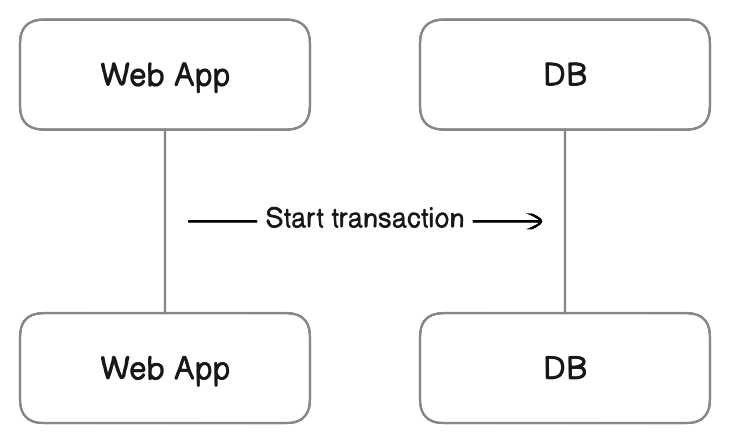
Here are the types of arrows:
| Arrow | Syntax | Description |
|---|---|---|
> |
Left-to-right arrow | |
< |
Right-to-left arrow | |
<> |
Bi-directional arrow | |
 |
- |
Line |
 |
-- |
Dotted line |
--> |
Dotted arrow |
Each line is parsed in sequential order from top to bottom and rendered in the diagram the same way.
Column names are required to be unique. If a line refers to a column name that hasn't been used in prior lines, a new column will be created.
Properties
Properties are key-value pairs enclosed in [ ] brackets that can be appended to column names. Properties are optional.
It is possible to set multiple properties like shown below:
Web App [icon: monitor, color: blue] > DB [icon: database, color: green]: Start transaction 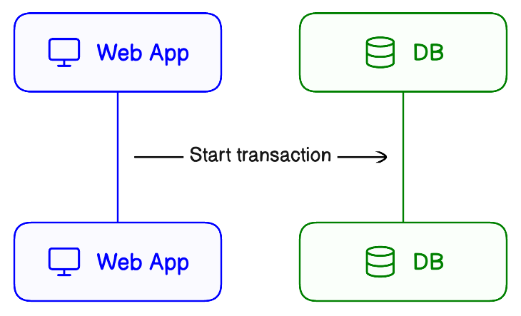
Here are the properties that are allowed on columns:
| Property | Description | Value | Default value |
|---|---|---|---|
icon | Attached icons | Icon names (e.g. aws-ec2). See Icons page for full list. | |
color | Stroke and fill color | Color name (e.g. blue) or hex code (e.g. #000000) | |
label | Text label | Any string. Enclose in double quotes (e.g. "Main Server") if containing a space. Allows multiple columns to have the same label. | |
link | Internal or external link | A fully fledged URL. Enclose in double quotes (e.g. "https://my-internal-docs.io/api-docs". Supports the full gamut of external links and Eraser-specific links: diagrams, headers, and files in Eraser. | |
colorMode | Fill color lightness | pastel, bold, outline | pastel |
styleMode | Embellishments | shadow, plain, watercolor | shadow |
typeface | Text typeface | rough, clean, mono | rough |
Here are the lists of icon names:
The label property is useful if you want the column label and name to be distinct. By default, the label is set as the column name. But because column names are required to be distinct, you will need to use the label property if you have two column with the exact same label.
// Names need to be distinct, but labels can overlap
Server1 [label: server]
Server2 [label: server]
Here are the properties that are allowed on arrows (lines):
| Property | Description | Example |
|---|---|---|
color | Line color | Web App > DB: Start transaction [color: blue]Web App > DB: [color: blue] |
Refer to Styling for more details and examples on the colorMode, styleMode, and typeface properties.
Blocks
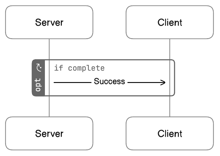
Blocks are groupings of messages that represent control flow. They can be used to express loops, if-else logic, parallel processing, and break execution.
Block definitions consist of a block type followed by { }. It can have an optional label property. For example, the below opt (optional) block has a label if complete. The block contains a single message from Server to Client.
opt [label: if complete] {
 Server > Client: Success
}
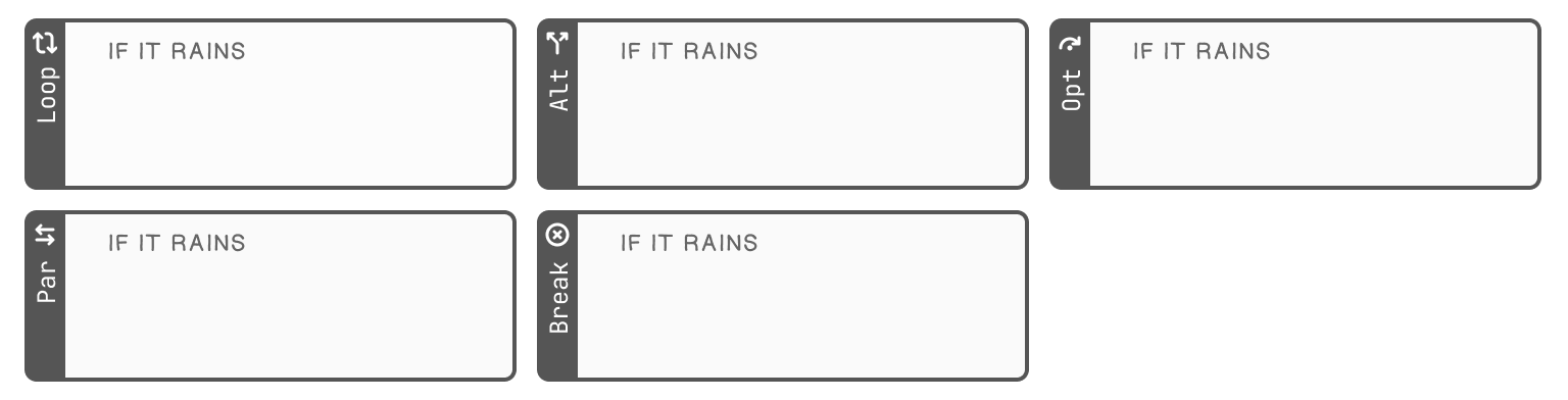
There are 5 block types, each representing a type of control flow.
| Type | Description |
|---|---|
loop | Loop |
alt (else) | Alternative |
opt | Optional |
par(and) | Parallel |
break | Break |
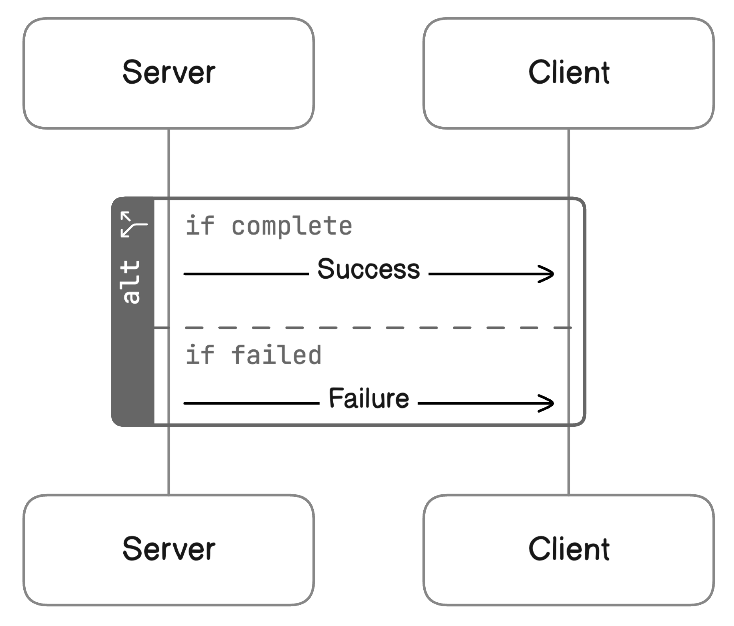
It is possible to create connected blocks in the case of the alt (paired with else) and par (paired with and) blocks.
alt [label: if complete] {
 Server > Client: Success
}
else [label: if failed] {
 Server > Client: Failure
}
Here are all the block properties that are allowed:
| Property | Description | Value |
|---|---|---|
label | Add a label to the block | Block label. Can be any string. |
icon | Add an icon to the block label | Icon names (e.g. aws-ec2). See Icons page for full list |
color | Specify a color for the block | Color name (e.g. blue) or hex code (e.g. #000000) |
Activations
Activations represent the time during which a column (an actor or resource) is actively performing an action.
A pair of activate and deactivate statements define a single activation. The activate and deactivate keyword is followed by the column name.
Client > Server: Data request
activate Server
Server > Client: Return data
deactivate Server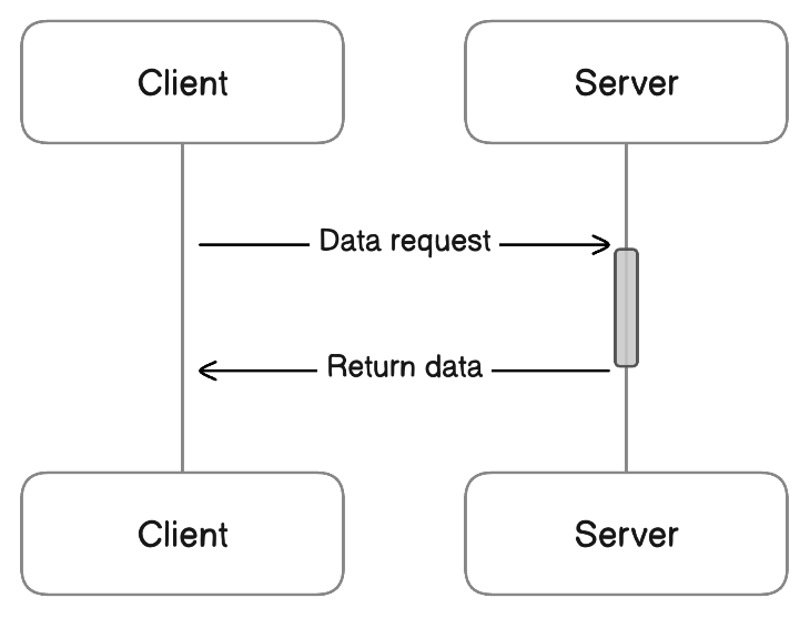
Escape string
Certain characters are not allowed in node and group names because they are reserved. You can use these characters, you can wrap the entire node or group name in quotes " ".
User > "https://localhost:8080": GETStyling
Styles can be applied at the diagram level. Below is an overview of the options and syntax. Refer to Styling for more details and examples.
| Property | Values | Default value | Syntax example |
|---|---|---|---|
colorMode | pastel, bold, outline | pastel | colorMode bold |
styleMode | shadow, plain, watercolor | shadow | styleMode shadow |
typeface | rough, clean, mono | rough | typeface clean |
autoNumber | on, nested, off | off | autoNumber on |
Legends
Legends map a swatch (connection, icon, shape, or color) to a label. Swatches are not tied to actual elements in the diagram.
 legend {
    [connection: -->, label: Async]
    [color: red, label: Error]
    [icon: aws-lambda, label: Lambda]
    [shape: diamond, label: Decision]
  }
Legend properties
| Property | Description | Value | Default Value |
|---|---|---|---|
| position | Position of the legend on the canvas | Position names (e.g. top-left or right) | top-right |
  legend [position: bottom-left] {
    [color: red, label: Error]
  }
Here is the list of positions:
top-left, top-right (default), bottom-left, bottom-right, top, bottom, left, right
Legend item properties
Each legend item is enclosed in [ ] and must include a label and at least one swatch property.
| Property | Description | Value |
|---|---|---|
| label | Text label | Any string. Enclose in double quotes if containing a space. |
| connection | Connection swatch | Connection types (e.g. --> or <>). See Connections above. |
| color | Color swatch | Color name (e.g. blue) or hex code (e.g. "#000000") |
| icon | Icon swatch | Icon names (e.g. aws-ec2). See Icons page for full list. |
| shape | Shape swatch | Shape names (e.g. diamond or oval). |
color can be combined with connection or shape. Other swatch types are mutually exclusive.
legend {
    [connection: -->, color: orange, label: Async backup]
    [shape: rectangle, color: blue, label: Active]
}
Updated 5 months ago